
What Does Antenna Gain Really Mean For IoT Cellular Connectivity?
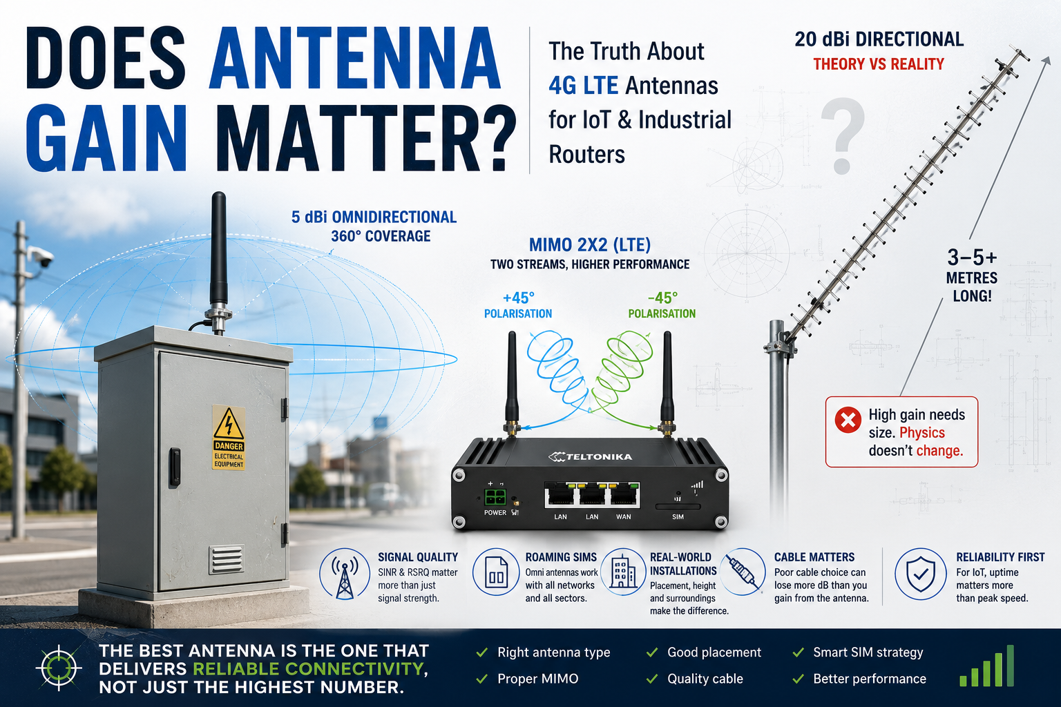
If you have spent any time searching for a 4G or 5G antenna online, you will have seen products claiming 9 dBi, 12 dBi, 15 dBi and even 20 dBi gain. The natural assumption is that higher numbers mean better performance.
In most IoT installations, that assumption is wrong.
Antenna gain is one of the most misunderstood concepts in industrial connectivity. It is also one of the most abused marketing terms in the industry. Buyers spend hours comparing gain figures while overlooking the factors that actually determine whether an installation works reliably for five or ten years.
This guide explains what antenna gain really means, why chasing high gain figures often leads to worse outcomes in IoT deployments, and what you should be focusing on instead.
What Is Antenna Gain and What Does dBi Mean?
Antenna gain is measured in dBi – decibels relative to an isotropic radiator.
An isotropic radiator is a theoretical antenna that radiates energy perfectly equally in every direction. It cannot exist physically. It is simply a reference point.
When an antenna is rated at 5 dBi, it means the antenna concentrates energy in specific directions to produce five decibels more effective radiated power than that theoretical reference – in those directions.
The critical word is concentrates.
The antenna is not an amplifier. It does not create additional power. The router or modem is still transmitting exactly the same amount of energy. The antenna is simply redirecting it.
A useful analogy is light. A standard light bulb emits light equally in every direction. A torch focuses that same light into a narrower beam. A laser narrows it further still. The amount of energy has not changed. It has simply been concentrated into a smaller area.
Antennas work in exactly the same way.
Why High Gain Cannot Come From Nowhere
This is where antenna marketing starts to break down.
High gain requires physical size. It requires a larger effective aperture. It requires more physical structure. Gain cannot appear from nowhere, and the laws of physics have not changed regardless of what is printed on a product listing.
A genuinely high-gain directional antenna – say, a well-engineered 15 dBi Yagi for LTE – is a large piece of equipment. It is not a compact panel you mount on a street cabinet with two self-tapping screws.
Whenever you see a small, lightweight antenna claiming extremely high gain figures, it is worth approaching that specification with scepticism. In many cases the advertised figure represents a theoretical peak at a single favourable frequency rather than measured real-world performance across the full LTE band range from 700 MHz to 3800 MHz.
Reputable antenna manufacturers – companies like IoT Antenna, Poynting, Panorama Antennas and 2J Antennas – often quote what appear to be modest gain figures. This is not because their products are inferior. It is because they are quoting measured, honest performance rather than theoretical peaks. A genuine 5 dBi antenna from a reputable manufacturer will almost always outperform a cheap 20 dBi antenna from an online marketplace.
Decibels Are Logarithmic – The Numbers Are Misleading
Most people instinctively treat antenna gain as a linear scale. They assume a 12 dBi antenna is roughly twice as good as a 6 dBi antenna.
Decibels do not work that way.
Every 3 dB represents a doubling of power. So the difference between 6 dBi and 12 dBi is not a factor of two – it is a factor of sixteen. In theory.
But here is the catch. That energy has to come from somewhere. In a high-gain antenna it comes from squeezing the radiation pattern into a very narrow vertical beam. The antenna becomes extremely directional. Energy that used to radiate upwards, downwards and at angles is now forced toward the horizon.
For a rural fixed wireless broadband installation with a known mast location, this can be genuinely useful.
For a utility cabinet on a suburban street, an EV charger on a car park, or a water monitoring station in a field, it creates problems you may not have anticipated.
The IoT Installation Reality
Most IoT devices are installed in situations that look nothing like a fixed wireless broadband deployment.
Think about where IoT routers and modems actually end up:
- Roadside utility cabinets
- EV charge point enclosures
- CCTV poles and traffic monitoring systems
- Smart metering installations
- Environmental monitoring stations
- Remote pump telemetry
- Smart agriculture sensors and gateways
- Construction site temporary power and monitoring
- Building management systems
- Industrial plant rooms
In the vast majority of these environments, the installer has one visit, limited time, and no ability to conduct a detailed RF site survey. The installation needs to work on the day and continue working reliably for years with minimal maintenance.
In that context, a large directional Yagi antenna requiring precise alignment is not just impractical. It can actively make the installation less resilient.
Why Roaming SIM Cards Change Everything
This is the point where many generic antenna guides become almost useless for IoT applications.
Traditional antenna advice assumes you are connecting to a known network on a known mast. You identify the nearest EE or Vodafone tower, you point your directional antenna at it, and you maximise RSRP.
The majority of serious IoT deployments do not work this way.
Industrial IoT applications frequently use multi-network SIM cards, roaming SIM cards, multi-IMSI SIMs or eSIM connectivity profiles that can switch between operators based on coverage conditions. The network serving the device today may not be the network serving it in six months. Following a network event, a cell outage or a planned mast upgrade, the SIM may roam onto a different operator serving from a completely different direction.
If you have installed a directional antenna aimed at a specific mast sector, you may have just reduced your network resilience rather than improved it.
Consider this scenario. A roaming SIM connects to EE today via a mast to the north-east. Six months later, local conditions change and the SIM roams to Vodafone, which is served from a sector to the south-west. A directional antenna aimed north-east is now actively working against you.
This is a real operational problem that rarely gets discussed in antenna marketing materials.
The Goal Is Availability, Not Maximum Signal Strength
This is perhaps the most important distinction in IoT connectivity, and it is one that the antenna industry almost never talks about.
The goal of most IoT installations is not to achieve the highest possible RSRP reading.
The goal is maximum availability – a connection that stays up, reports data reliably, and requires minimal intervention over a multi-year deployment.
A utility company monitoring a remote asset would typically prefer -95 dBm with access to three networks than -75 dBm locked to a single operator. The weaker but more flexible connection is more resilient. It is more likely to remain operational through network outages, planned maintenance and changing coverage conditions.
A telemetry device sending a 200-byte payload every fifteen minutes does not need maximum throughput. It needs a connection that is there when it needs to send.
Once you reframe the objective from “maximum signal” to “maximum availability”, the antenna conversation changes completely.
Why MIMO Often Matters More Than Gain
Modern LTE networks use MIMO – Multiple Input Multiple Output.
Rather than transmitting a single data stream, the network transmits two or more independent streams simultaneously. The router processes these streams separately, which increases throughput and improves connection robustness.
Most modern LTE industrial routers use 2×2 MIMO. Many 5G-capable routers support 4×4 MIMO.
This matters enormously for antenna selection.
Most LTE routers have two cellular antenna ports. These are not simply for signal diversity in the traditional sense. The modem expects to receive independent spatial streams on each port. The two antenna elements should ideally be cross-polarised – typically at plus and minus 45 degrees – to maximise the independence of the received signals.
An installer who connects a single high-gain antenna to only one port while leaving the second port disconnected or terminated has immediately halved the potential throughput of the modem, regardless of how high the gain figure is on that antenna.
In many real-world installations, switching from a single high-gain antenna to a properly implemented 2×2 MIMO antenna system produces a larger performance improvement than any reasonable increase in gain could have delivered.
For 5G deployments requiring 4×4 MIMO, this effect is even more pronounced. You can find more detail on MIMO antenna selection and industrial router compatibility at IoT Portal.
Why Placement Beats Gain Almost Every Time
Experienced installers know something that antenna marketing materials rarely admit.
Moving an antenna by 30 centimetres can sometimes produce a larger improvement than switching to a higher-gain antenna.
Radio waves create complex interference patterns. Reflections from nearby metal structures, interference from electrical equipment, and multipath cancellation effects can create deep signal nulls at specific points in space. Moving the antenna slightly can shift it out of a null and into a significantly stronger signal environment.
The most common installation mistakes are not related to insufficient gain. They are:
- Antenna mounted too low, below the top of the cabinet
- Antenna mounted directly against a metal surface with no clearance
- Antenna positioned adjacent to electrical switchgear or inverters
- Antenna inside a steel enclosure rather than external
- Poor cable quality consuming the available gain
- Only one MIMO port connected
- Water ingress degrading the cable assembly over time
In the majority of cases where an installer reports that a “high-gain” antenna has not improved performance, one or more of these factors is the real cause.
The Cable Loss Problem Nobody Mentions
Every metre of coaxial cable introduces signal loss.
Standard RG58 cable loses approximately 0.5 to 0.6 dB per metre at LTE frequencies. A 10-metre cable run can consume 5 or 6 dB of your system budget before the signal even reaches the modem.
If you specified a 12 dBi antenna to overcome a difficult signal environment, but installed it using 10 metres of RG58, you may have a system gain of only 6 or 7 dBi – not significantly better than a quality 5 dBi antenna with a short, high-quality cable run.
This is why the antenna and cable should always be treated as one system. Low-loss cable types such as LMR195, LMR240 and LMR400 exist precisely because cable loss is a real and significant factor in antenna system design.
Shorter cable runs with higher-quality cable often outperform longer runs with nominally higher-gain antennas.
Building Materials and Why External Antennas Work
One of the most reliable improvements available in any IoT installation is simply moving the antenna to the outside of the building or enclosure.
The improvement is not primarily because of antenna gain. It is because the antenna is no longer trying to receive signals through attenuating materials.
Common building materials introduce significant signal loss:
- Standard brick walls – moderate attenuation
- Reinforced concrete – heavy attenuation
- Steel cladding and metal enclosures – very heavy attenuation
- Foil-backed insulation – can be almost completely blocking
- Modern energy-efficient glazing with metallic coatings – surprisingly attenuating
Many industrial sites and plant rooms effectively behave as partial Faraday cages. A router inside a steel cabinet in a substation may be receiving a fraction of the signal available just outside the cabinet door.
In these scenarios, a modest external omnidirectional antenna connected via a short low-loss cable to the router will deliver a dramatic improvement – not because of its gain specification, but because it has relocated the receive point to a position where signals can actually reach it.
When Directional Antennas Are the Right Answer
None of this means directional antennas are never appropriate. They are genuinely the correct solution in specific circumstances.
A directional antenna makes sense when:
- The installation is in a rural area with one clear serving mast and very weak signal
- The deployment uses a single fixed network operator with no roaming
- A proper site survey has identified the serving cell and its location
- The installation is fixed and will not be subject to network changes
- Extreme signal conditions genuinely require the additional gain
In rural agricultural monitoring, remote infrastructure telemetry on moorland or upland sites, and long-distance point-to-point links, a quality directional antenna can transform an unusable connection into a reliable one.
The key is selecting a directional antenna because the application genuinely requires it – not because a larger gain number looks impressive on a specification sheet.
What Good Antenna Selection Actually Looks Like
For the majority of IoT deployments – and this covers probably 80 percent of real-world installations – the optimal antenna specification is straightforward:
- Quality omnidirectional antenna from a reputable manufacturer
- Proper 2×2 MIMO implementation with two antenna elements
- External mounting above the top of the cabinet or enclosure
- Short cable run using quality low-loss coaxial cable
- Roaming SIM or multi-network SIM for operator flexibility
- Industrial router with proper MIMO modem support
That combination will outperform a cheap high-gain antenna poorly installed on a single port, connected via a long RG58 cable run, pointed at a single mast sector, using a locked single-network SIM.
Every time.
For a wider range of antenna options suited to industrial IoT and M2M applications, IoT Antenna covers everything from compact omnidirectional MIMO antennas to specialist outdoor directional antennas for challenging rural deployments.
Summary: What to Focus On Instead of Gain
Antenna gain is a useful specification. It is not the most important specification for IoT installations.
The questions worth asking when specifying an antenna are:
- Does this installation use a roaming or multi-network SIM? If yes, directional antennas introduce resilience risk.
- Is the antenna outside the enclosure? If not, that should be the first priority.
- Are both MIMO ports being used correctly? A properly implemented MIMO system matters more than headline gain.
- What is the total cable loss in the system? A short run of quality cable often beats a long run of cheap cable with a higher-gain antenna.
- Is the antenna from a manufacturer that publishes measured gain across the full LTE frequency range? If not, the gain figure may not reflect real-world performance.
The best-performing IoT installations are rarely the ones with the biggest antennas. They are the ones where the antenna, router, SIM card, cable and installation position have been considered together as a complete system.
For more on roaming SIM cards and multi-network connectivity for IoT deployments, visit Roaming Sims. For in-depth technical guides on IoT connectivity, router configuration and cellular network engineering, visit IoT Portal.
Written by Peter Green. Peter has over two decades of experience in cellular connectivity, IoT infrastructure and antenna engineering for industrial and M2M applications.